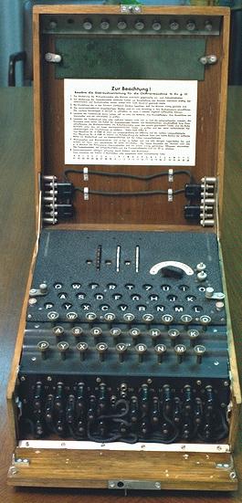
The Enigma machine, see the above photograph, was a rotary electromechanical enciphering device, which superficially resembled a typewriter.
There were many variants of the Enigma, but the most common version, and the version described here, is the standard Army and Luftwaffe machine. Its main components were; a keyboard, a lampboard, a stecker or plugboard, and a set of five rotors.
The keyboard consisted of only 26 keys, each of which represented a letter of the alphabet. There was no upper or lower case, numerals, punctuation marks, carriage return or space.
The lampboard consisted of 26 glowlamps, each of which, when illuminated, indicated a letter by shining through a small window printed with a letter of the alphabet.
The plugboard consisted of 26 sockets, each of which had a letter printed adjacent to it. To connect the sockets there were ten leads, or steckers, with a plug at each end. When a lead was plugged into, say, the Q and R sockets, it had the effect of swapping them, so that a current which represented Q as it entered the steckerboard, represented R when it emerged, and a current which represented R as it entered the steckerboard represented Q when it emerged. The sockets had a sprung arrangement such that, if no jack occupied the socket, that is, if a letter was unsteckered, it nevertheless made an electrical connection. For example, if the Z socket was unoccupied, the Z key was nevertheless connected to the Z entry position to the right rotor.
To facilitate the reciprocal operation of the stecker, each socket consisted of one large and one small hole. Each lead contained two insulated wires and each plug had two jacks, one larger than the other, to fit the large and small holes in the socket. Note that there was no necessity to design the Enigma with a reciprocal steckerboard. If the steckerboard had not been reciprocal Turing's method of defeating it which we shall discuss later would not have worked. Thus the reciprocal steckerboard was a serious design flaw.
Since there were only ten leads, six letters remained unsteckered. Surprisingly, the number of permutations afforded by this arrangement is greater than the number of permutations if all 26 letters are steckered. The greatest number of permutations is attained when there are eleven leads. It is not known why the Germans used only ten. The rotors, which were about 4 inches in diameter, had 26 spring-loaded pins on the right hand side and 26 contact-pads on the left. The pins were internally wired to the contact-pads in an apparently irregular way. For example, pin 1 might be wired to pad 17, pin 2 might be wired to pad 8, pin 3 might be wired to pad 23, and so on. The pattern of the wiring was different in each of the five rotors and in order to readily distinguish which rotor was which, they were stamped with a Roman numeral. The rotors were therefore named I, II, III, IV and V.
Each rotor was encircled by a rotatable ring which could be clicked into any one of 26 discrete positions and then secured in that position by a clip. The ring was labelled with the 26 letters of the alphabet, or in some versions of the Enigma, the numerals 01-26, and had a notch cut into it to allow it to be engaged by a pawl. The position of the notch depended on which rotor the ring was attached to. For rotor I the notch was adjacent to Y; for rotor II, M; for rotor III, D; for rotor IV, R; and for rotor V, H. This meant that the notches were engaged when Q, E, V, J and Z were uppermost on rotors I, II, III, IV, and V respectively and that therefore the turnover positions were R, F, W, K, A, remembered by the cryptanalysts at Bletchley Park by the mnemonic Royal Flags Wave Kings Above. There was a ratchet on the right side of each rotor which could also be engaged by a pawl.
Three of the five rotors would be selected to be fitted in the machine at any one time. The three rotors were put on a spindle in a predetermined order and then clamped into the Enigma.
To the left of the left rotor there was the Umkehrwalze, a static configuration of 13 wires each of which connected one of the left rotor's contact-pads to another of its contact-pads. The set of three rotors and the Umkehrwalze collectively comprise the scrambler.
When the operator pressed a key, one or more of the rotors stepped in a manner similar, but not identical, to that of an odometer. Current then flowed from the keyswitch through one wire in one of the stecker leads then successively through the right, middle and left rotors, then into and back out of the Umkehrwalze, back through the left, middle and right rotors and then through a second stecker lead before finally illuminating one of the glowlamps and thus indicating a letter. Figure 2.1 shows the electrical pathways through the Enigma.
The stepping of the rotors was activated by three spring-loaded pawls. When a key was pressed a rotor stepped if a pawl engaged either its ratchet, or the notch in its ring. Due to their relative rate of rotation, the left, middle and right rotors are often referred to as the slow, middle and fast rotors respectively.
The right pawl engaged only the fast rotor, the middle pawl was shared by the middle and fast rotors, and the left pawl was shared by the middle and slow rotors. When a key was pressed all three pawls pushed together. Since the right pawl always engaged the ratchet on the fast rotor, the fast rotor stepped whenever a key was pressed.
The middle pawl rode on the fast rotor's ring. When the fast rotor stepped into a position which allowed the pawl to snap into the notch in its ring, the middle pawl engaged the middle rotor's ratchet, so the next key press stepped the middle rotor.
Similarly, the left pawl rode on the middle rotor's ring. When the middle rotor stepped into a position which allowed the pawl to snap into the notch in its ring, the left pawl engaged the slow rotor's ratchet, so the next key press stepped the slow rotor.
When the middle pawl snapped into the fast rotor's notch, it engaged the middle rotor's ratchet. So the next key press stepped the middle rotor, but if, as a consequence of this step, the middle rotor stepped into a position which caused the left pawl to snap into the notch in its ring, the key press after that would then step:
1. The fast rotor, because its ratchet is engaged by the right pawl
2. The middle rotor, because its notch is engaged by the left pawl
3. The slow rotor, because its ratchet is engaged by the left pawl
So, in this case, all three rotors stepped. Thus the middle rotor has stepped in successive key presses, an action referred to as double-stepping.
It is this complication that ensures that the stepping mechanism of the Enigma is not equivalent to that of a simple odometer.
Copyright © Graham Ellsbury 1998
Continue to Part 3. How the Enigma was Set Up and Operated
Return to The Enigma and the Bombe main page