 |
 |
|
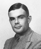
Alan Turing |
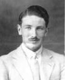
Gordon Welchman
Discovered the diagonal board |
|
|
|
|
Alan Turing |
Gordon Welchman
Discovered the diagonal board |
Due to its complexity, the circuitry of the bombe does not readily lend itself to being diagrammed. But to obtain a clear understanding of how the bombe was plugged up and how it worked, it is advantageous to examine a circuit diagram for the entire bombe. For the real bombe, this is impractical without resorting to large-scale diagrams, but there is an alternative, we can conveniently diagram the complete circuitry of a simplified bombe.
We shall accordingly consider a simplified bombe designed to search for keys for a simplified Enigma with an alphabet of only eight letters: A, B, C, D, E, F, G and H. The principles by which the simplified bombe operates are identical to those of the real bombe.
Suppose we have obtained the crib BEACHHEAD which we have paired, as described earlier, with the ciphertext EDBGEAHDB as follows:
| 1 | 2 | 3 | 4 | 5 | 6 | 7 | 8 | 9 |
| B | E | A | C | H | H | E | A | D |
| E | D | B | G | E | A | H | D | B |
Then, also as described earlier, we can derive the crib diagram:
This diagram, which is called a menu, tells us all we need to know to plug-up the bombe.
After Turing had designed the bombe, Gordon Welchman, a colleague of Turing's at Bletchley Park, realised the reciprocal property of the stecker meant that if, for example, W was steckered to Q then Q must be steckered to W, and that it was possible to reflect this property in a device which came to be called the diagonal board.
The diagonal board consisted of 26 cables each containing 26 wires leading into and out of it, with a total of 325 connections between them. For example, the a wire in the B cable was permanently connected to the b wire in the A cable, and the a wire in the C cable was permanently connected to the c wire in the A cable, and so on.
As shown in Figure 3.2, the diagonal board of our simplified bombe has 8 cables each containing 8 wires.
The effect of the diagonal board, when attached to the bombe, was to increase the feedback into the double-ended scramblers and thus reduce the necessity of obtaining loops in the crib-ciphertext pairing. This in turn made it possible to use shorter menus which were less likely to include a turnover of the Enigma's middle rotor during the encipherment of the plaintext. This is highly advantageous for reasons that will appear later.
The two ends of a double-ended scrambler were plugged into the two cables of the diagonal board which represented the two letters connected by the scrambler in the menu. In other words, each scrambler bridges two of the diagonal board's cables. When all the scramblers had been connected in this way the drums were rotated into positions in accordance with their relative positions shown in the menu.
In our example menu, B is connected to E at relative position 1, so one end of a double-ended scrambler is plugged into the diagonal board's cable which represents B, and the other end of the same double-ended scrambler is plugged into the diagonal board's cable which represents E. Similarly, a second double-ended scrambler is plugged to bridge D and E; a third to bridge A and B; a fourth, C and G; a fifth, E and H; a sixth, A and H; a seventh, E and H again; an eighth, A and D; then the ninth and final double-ended scrambler, bridges B and D.
Next we mount the drums on their shafts. We first select a particular rotor order to try. Suppose we try rotors I, II and III. We mount nine drums each of which corresponds to rotor I on the first nine top shafts in a battery, then we mount nine drums each of which corresponds to rotor II on the first nine middle shafts in the same battery, then we mount nine drums each of which corresponds to rotor III on the first nine lower shafts in the same battery.
The drums must now be rotated to their appropriate positions. So we rotate each drum until it has the letter A painted on its circumference in the 12 o'clock position. To reflect their relative positions in the crib-ciphertext pairing the drums are now reset in accordance with the following table:
|
drum
|
cables connected by drum's scrambler
|
scrambler position in crib-ciphertext pairing
|
drums letter in 12 o'clock position
|
|
top
|
B and E
|
1
|
A
|
|
top
|
D and E
|
2
|
B
|
|
top
|
A and B
|
3
|
C
|
|
top
|
C and G
|
4
|
D
|
|
top
|
E and H
|
5
|
E
|
|
top
|
A and H
|
6
|
F
|
|
top
|
E and H
|
7
|
G
|
|
top
|
A and D
|
8
|
H
|
|
top
|
B and D
|
9
|
A
|
|
middle
|
B and D
|
9
|
B
|
This completes the plugging-up of a single battery.
See Figure 3.3
The other two batteries are now plugged up in exactly the same way except that different drum orders are selected.
Note that the loops in the menu are represented by loops in the plugged-up bombe.
The bombe is now fully plugged up and ready to run.
Copyright © Graham Ellsbury 1998
Continue to Part 4. How the Bombe Worked
Return to The Enigma and the Bombe main page